
bleeding hydraulic system on a ghs system pdf
Understanding GHS Hydraulic Systems & Bleeding
GHS hydraulic systems require periodic maintenance, including bleeding to remove trapped air, ensuring optimal functionality and preventing damage. Detailed PDF guides assist technicians.

What is a GHS Hydraulic System?
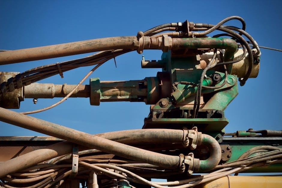
GHS hydraulic systems are closed-loop power transmission systems commonly found in various industrial and mobile applications, notably in equipment like buggies and certain types of machinery. These systems utilize pressurized hydraulic fluid – typically oil – to transmit force and motion. A core component is the hydraulic pump, often a Hydro-Gear model like the WBH16EF, which generates the necessary pressure.
Understanding these systems is crucial for effective maintenance, particularly procedures like bleeding. Bleeding involves removing air bubbles from the hydraulic lines and components. Air ingress can severely compromise performance, leading to spongy operation, reduced efficiency, and potential damage. Detailed PDF documentation, often provided by manufacturers, outlines the specific procedures for each GHS system, ensuring safe and correct operation. Proper bleeding restores responsiveness and extends the system’s lifespan.
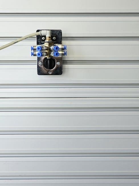
Components of a Typical GHS System
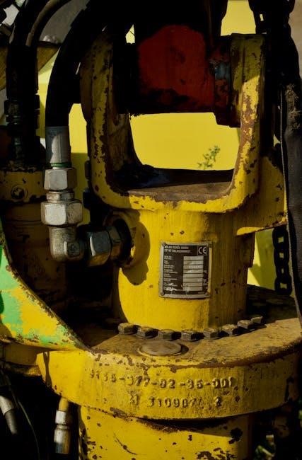
A typical GHS hydraulic system comprises several key components working in unison. These include a hydraulic reservoir to store the fluid, a pump – frequently a Hydro-Gear unit like the WBH16EF – to generate pressure, and a network of hoses and pipes for fluid transmission. Crucially, hydraulic cylinders (single or double-acting) convert fluid pressure into mechanical force.
Valves regulate fluid flow and direction, while filters maintain fluid cleanliness. Understanding each component’s role is vital for troubleshooting and maintenance, including bleeding the system. PDF manuals often provide exploded diagrams illustrating these parts. Air trapped within these components, particularly cylinders and lines, necessitates bleeding to restore optimal performance. Correctly identifying each part aids in locating bleed points and following the manufacturer’s recommended procedures detailed in the system’s documentation.

Why Bleeding a Hydraulic System is Necessary
Bleeding removes air bubbles that compromise hydraulic efficiency, causing sluggish operation and potential damage; PDF guides detail proper procedures for GHS systems.
Air in the System: Causes & Effects
Air ingress into a GHS hydraulic system stems from several sources, including loose fittings, damaged seals, or low fluid levels during operation or maintenance. A PDF guide emphasizes identifying these entry points. The effects of trapped air are significant; it reduces system efficiency by compressing under pressure, leading to spongy or erratic actuator movement.
This compressibility diminishes the system’s ability to deliver consistent force, impacting performance. Furthermore, air accelerates fluid degradation and can cause cavitation – the formation and collapse of vapor bubbles – which damages hydraulic components over time. Consistent bleeding, as outlined in system PDF documentation, is crucial to mitigate these issues and maintain optimal hydraulic function, preventing costly repairs and downtime.
Recognizing the Symptoms of Air Entrapment
Identifying air within a GHS hydraulic system is vital for timely intervention. Common symptoms include a spongy or inconsistent feel when operating controls, causing jerky or delayed responses. A detailed PDF manual highlights these indicators. Unusual noises, such as hissing or whining sounds, often signify air bubbles collapsing within the hydraulic fluid.
Reduced lifting capacity or difficulty maintaining position under load are also telltale signs. Furthermore, the system may exhibit increased operating temperatures due to reduced efficiency. Consulting the system’s PDF troubleshooting guide can help pinpoint the source of the air. Promptly addressing these symptoms through proper bleeding procedures, as detailed in the documentation, prevents further damage and restores optimal performance.
Tools and Materials Required for Bleeding
Bleeding a GHS system necessitates specific tools: hydraulic oil (refer to PDF specs), a bleeding kit, wrenches, and containers for safe fluid disposal.
Hydraulic Oil Specification for GHS Systems
Selecting the correct hydraulic oil is paramount for GHS system performance and longevity. Referencing the system’s PDF documentation is crucial, as specifications vary between models. Generally, GHS systems require a high-quality hydraulic oil with a viscosity grade between ISO 32 and ISO 46, depending on ambient operating temperatures.
The oil must possess excellent anti-wear properties, oxidation stability, and demulsibility (water separation). Synthetic oils are often recommended for extended service intervals and superior performance in extreme conditions. Avoid using oils containing additives incompatible with system seals, potentially causing swelling or degradation. Always verify compatibility before introducing any new fluid. Using the incorrect oil can lead to component failure, reduced efficiency, and void warranties. Consult the PDF manual for precise oil type recommendations.
Bleeding Kit & Accessories
A comprehensive bleeding kit streamlines the process and minimizes mess. Essential components include a hydraulic oil reservoir with a filter, clear tubing of appropriate diameter to connect to bleeder ports, and various fittings for compatibility with GHS system connections; The system’s PDF manual often details specific fitting requirements.
Additional useful accessories are a hand pump to assist in fluid circulation, a drip pan to contain spilled oil, and clean rags for wiping surfaces. A torque wrench ensures proper tightening of fittings, preventing leaks. Some kits include a pressure gauge for monitoring system pressure during bleeding. Always refer to the PDF guide for recommended tools. Having the correct kit readily available saves time and ensures a safe, efficient bleeding procedure, maximizing system performance.
Step-by-Step Bleeding Procedure ─ General Approach
Consult the GHS system’s PDF manual for detailed instructions; generally, this involves loosening bleeder valves while operating the hydraulic system to expel air.
Safety Precautions Before Starting
Prior to initiating any hydraulic system bleeding procedure, referencing the GHS system’s PDF documentation for specific safety guidelines is paramount. Always wear appropriate personal protective equipment (PPE), including safety glasses and gloves, to shield against potential oil splashes and hydraulic fluid injection injuries.
Ensure the work area is clean, well-lit, and free of obstructions. Implement Lockout/Tagout procedures to de-energize the system and prevent accidental operation during bleeding. Never attempt to bleed a system under pressure; relieve all pressure first, following the PDF’s instructions for “bleeding down” the system.
Be mindful of hot surfaces, especially near the pump or engine. Properly dispose of any collected hydraulic fluid according to local environmental regulations. A thorough understanding of the system and adherence to safety protocols, as outlined in the PDF, are crucial for a safe and successful bleeding process.
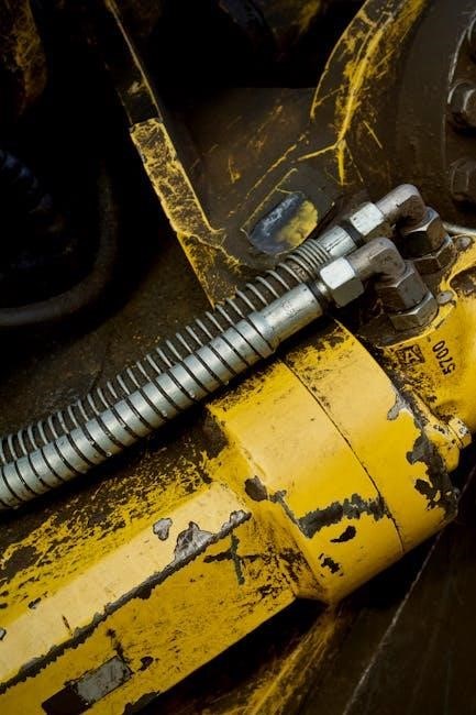
Identifying Bleeder Valves & Ports
Locating the correct bleeder valves and ports is critical for effective hydraulic system bleeding, and the GHS system’s PDF manual is your primary resource. These valves are typically small, often featuring a screw or cap, strategically positioned at high points within the hydraulic lines and on the hydraulic cylinder itself.
Refer to the PDF’s diagrams to pinpoint the exact location of each bleeder valve, as their appearance and placement can vary depending on the specific GHS model. Double-acting cylinders will have at least two bleeder ports – one for each side of the piston.
Ensure you correctly identify the bleeder valves before loosening them, as incorrect ports could lead to complications. The PDF may also detail specific tools required for opening these valves without damaging them. Careful identification, guided by the PDF, prevents errors and ensures a smooth bleeding process.

Bleeding a Double-Acting Hydraulic Cylinder
Double-acting cylinders require a specific bleeding sequence, detailed in the GHS system PDF, to expel air from both sides of the piston effectively.
Procedure for Double-Acting Cylinder Bleeding
Refer to the GHS system PDF for detailed diagrams and specific instructions tailored to your model. Begin by ensuring the system is safely de-energized and locked out. Locate the bleeder valve(s) on the cylinder – typically one at each port.
Connect clear tubing to the bleeder valve and submerge the other end in a container partially filled with clean hydraulic oil. Slowly open the bleeder valve, allowing fluid and air to escape.
Extend and retract the cylinder rod manually (or using the system’s controls if safely possible) while continuously monitoring the fluid flow for air bubbles. Close the bleeder valve when only clean fluid, free of air, is observed. Repeat this process for each bleeder valve, ensuring complete air removal. The PDF will illustrate proper valve locations and sequencing.
Troubleshooting Common Issues During Bleeding
If air continues to be present after repeated bleeding attempts, consult the GHS system PDF for specific troubleshooting steps. Persistent air may indicate a leak in a hydraulic line, seal, or within the cylinder itself. Carefully inspect all connections and components for visible leaks.
Another common issue is insufficient hydraulic fluid; ensure the reservoir is adequately filled. If the cylinder still operates erratically, a faulty valve or pump could be the cause – the PDF may contain diagnostic flowcharts.
Stubborn air pockets might require cycling the cylinder through its full range of motion multiple times during the bleeding process. Always prioritize safety and refer to the PDF for model-specific guidance.
Specifics for Hydro-Gear Pump System Bleeding (WBH16EF)
WBH16EF Hydro-Gear pump systems require a unique bleeding procedure; consult the official PDF instructions for detailed steps to ensure proper operation.
Hydro-Gear Pump Bleeding – Initial Setup
Prior to initiating the bleeding process for a Hydro-Gear pump (WBH16EF), meticulous preparation is crucial. Begin by verifying the hydraulic fluid level within the reservoir, ensuring it meets the manufacturer’s specifications as detailed in the system’s PDF documentation.
Confirm all connections are securely tightened, preventing potential leaks during operation. Disconnect the load from the hydraulic system to eliminate resistance during the bleeding procedure.
Familiarize yourself with the location of the bleed valve(s) – often found near the pump or hydraulic cylinders.
Have a clean container readily available to collect the expelled hydraulic fluid. Refer to the official PDF guide for specific setup instructions related to your WBH16EF model, as variations may exist.
Hydro-Gear Pump Bleeding – Detailed Steps
Following the initial setup, begin the bleeding process by slowly opening the bleed valve(s) on the Hydro-Gear pump (WBH16EF), referencing the detailed diagrams within the system’s PDF manual. Simultaneously, operate the pump control lever, extending and retracting the hydraulic cylinder.
Continue this operation until a steady stream of fluid, free of air bubbles, emerges from the bleed valve.
Carefully monitor the hydraulic fluid level in the reservoir, replenishing as needed to prevent pump cavitation.
Once air is purged, securely close the bleed valve(s). Consult the PDF guide for torque specifications. Repeat the process for any additional bleed points within the system, ensuring complete air removal for optimal performance.
Lockout/Tagout Procedures & Hydraulic Safety
Prior to bleeding, strict lockout/tagout procedures are crucial, as detailed in the system’s PDF manual, to safely relieve pressure and prevent accidental operation.
Importance of Lockout/Tagout During Maintenance
Lockout/Tagout (LOTO) is paramount when performing hydraulic system maintenance, specifically bleeding, on a GHS system. The PDF documentation emphasizes that hydraulic systems store significant potential energy under pressure. Failing to properly de-energize and isolate the system can lead to severe injury or equipment damage.
LOTO procedures involve physically disconnecting or isolating the energy source – in this case, the hydraulic pump – and applying locks and tags to prevent accidental activation. This ensures the system remains safely deactivated throughout the bleeding process. Referencing the GHS system’s PDF manual is critical for understanding the specific LOTO steps required for your model.
Bleeding down pressure, as outlined in the PDF, is a component of LOTO, but isn’t a substitute for complete isolation. Always verify zero pressure before commencing any work.
Bleeding Down Pressure as a Safety Measure
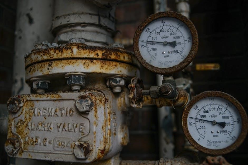
Before initiating any maintenance, including bleeding a GHS hydraulic system – as detailed in the system’s PDF manual – safely reducing system pressure is crucial. This “bleeding down” process eliminates stored energy, minimizing the risk of fluid ejection and potential injury. The PDF instructions will specify designated bleed points or procedures for your specific model.
Carefully open bleed valves, allowing hydraulic fluid to discharge into a suitable container. Always direct the fluid stream away from personnel and equipment. The PDF may outline specific valve opening sequences to prevent sudden pressure drops. Confirm complete pressure relief using a gauge before disconnecting any hydraulic lines or components.
Bleeding down pressure is not a replacement for full Lockout/Tagout procedures, but a vital supplementary safety step, as highlighted in the PDF documentation.
Post-Bleeding Checks & Maintenance
Post-bleeding, consult the PDF for leak checks and a maintenance schedule; regular inspections ensure continued optimal performance of the GHS hydraulic system.
Checking for Leaks After Bleeding
Following the bleeding procedure, a thorough inspection for hydraulic leaks is crucial. Refer to the GHS system’s PDF documentation for specific leak check points, typically focusing on connections at the pump, cylinders, valves, and hoses. Start the system and slowly operate all functions, carefully observing each component for any signs of fluid seepage.
Pay close attention to fittings, hose crimps, and cylinder seals. Even a small leak can indicate a problem and reduce system efficiency. Use a clean cloth to wipe around connections, making it easier to spot fresh leaks. If leaks are detected, immediately shut down the system and address the issue before continuing operation. Tighten fittings as needed, or replace damaged components according to the PDF’s recommendations.
Regular Hydraulic System Maintenance Schedule
Consistent maintenance, detailed in the GHS system’s PDF manual, is vital for longevity. Schedule hydraulic oil level checks monthly, and complete oil/filter changes every 250-500 operating hours, or annually, whichever comes first. Inspect hoses and fittings quarterly for wear, cracks, or leaks, replacing them proactively.
Include a hydraulic system bleed as part of your annual preventative maintenance, or whenever a component is replaced. Regularly check cylinder seals for damage. The PDF will outline specific intervals for inspecting and lubricating pivot points. Adhering to this schedule minimizes downtime, prevents costly repairs, and ensures optimal performance of your GHS hydraulic system, extending its operational life significantly.
Leave a Reply
You must be logged in to post a comment.